In order for a workpiece to be produced on a CNC machine, the control unit requires a programme. A CNC programme in accordance with DIN 66025 contains all the path and switching information as well as auxiliary commands required for machining and can be read by any CNC machine.
Image: Example of the sentence structure
Programme structure
A CNC programme in accordance with DIN 66025 consists of the programme number and blocks that describe the entire work sequence of the machine step by step. The individual blocks are processed one after the other from top to bottom. They are numbered consecutively, N1, N2, N3 ..., or in steps, e.g. N5, N10, N15 ... (N = number). The controller reads several records in advance so that it can perform arithmetic operations. If records are numbered in jumps, further records can be inserted in between without changing the following record numbers.
Sentence structure
A sentence consists of one or more words made up of an address letter and a number. The arrangement of the words in a sentence is known as the sentence format. A block begins with the block number. This is followed by the path conditions or other programme instructions.
The following instructions are required for the control of CNC machines:
Path conditions (G) that determine the type of movement, e.g. rapid traverse, linear or circular interpolation, plane selection, dimensioning type, corrections
Geometric instructions (X, Y, Z, I, J, K ...) for controlling the slide movements
Technological instructions (F, S, T) for defining the feed (F = feed), spindle speed (S = speed) and tool (T = tool)
Switching commands (M) for machine functions such as tool change, coolant supply and programme end
Cycle or sub-programme calls for frequently recurring programme sections
The meaning of the 1-digit travel conditions (G functions) is standardised in accordance with DIN 66025-2. Some numerical values are freely available to the control unit manufacturer.
The meaning of part of the switching function is also defined.
Route information
The G functions (G = geometric function) define how the tool should reach the subsequent target coordinates. Some G functions are active as soon as they are switched on and do not need to be programmed, e.g. G17, G40 and G90. This switch-on status depends on the control and machine. Stored (modal) G functions remain active until they are overwritten or cancelled by other G functions that work in the opposite direction.
The destination point to be approached is specified with the address letters of the corresponding axes and the coordinate values, e.g. X100 Y20. With most control units, the coordinate values are stored and effective. It is therefore not necessary to re-enter an unchanged value.
With circular interpolation, however, all target point coordinates must be specified, even if they are unchanged.
With path condition G94, the feed speed of the carriage corresponds to the value programmed under F. G95 means that the value programmed under F is executed as a feed in mm/revolution.
If G96 is programmed, the control unit regulates the speed of the work spindle so that the value programmed under S corresponds to the cutting speed vc. With G97, the speed of the working spindle is constant. It corresponds to the value programmed under S.
Example: G94 F200 Web speed 200 mm/min
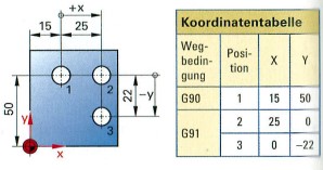
Image: Absolute dimensioning of a panel
Programming with absolute and incremental dimensions
When programming with Absolute dimensions (G90) all dimensions refer to the workpiece zero point. Subsequent changes to a position do not affect other travel dimensions.
Picture: Incremental dimensioning of drill holes
If required Incremental dimensioning (G91) can be switched . The dimensions refer to the previous position of the tool. The slide moves by the programmed dimension in a positive or negative direction (Increment = growth). Programming with incremental dimensions is independent of the workpiece zero point.
When programming with absolute dimensions (G90), all dimensions refer to the workpiece zero point
When programming with incremental dimensions (G91), the increment to the previous point is specified with the correct sign (incremental dimension).
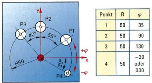
Programming with polar coordinates
Entering polar coordinates makes programming easier if the drawing contains angle information. For points P1 to P4, the controller requires the position of the pole, the radius R and the polar angle ø. Starting from the positive X-axis, the angle specification is positive in an anti-clockwise direction and negative in a clockwise direction.
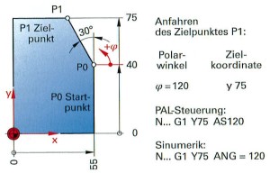
Programming with polar coordinates is possible with the Siemens controller (Sinumerik) and the DIN controller, for example. Target coordinates and the polar angle ø are entered.
Image: Bolt hole circle with polar coordinates
Straight line interpolation
If the path condition G01 is programmed, the target point is approached at the programmed feed rate. The tolerance centre must be specified as the coordinate value.
Picture: Workpiece contour with polar coordinates
Circular interpolation
If the carriage is to perform a circular movement, the controller requires the following three details in addition to the plane selection to calculate the path values:
Information on circular interpolation:
Direction of rotation G02 clockwise or G03 anti-clockwise
Coordinates of the target point (circle end point). These are always required, even if one of the target points of the circle is the same as the starting point.
Position of the centre of the circle by specifying the centre point parameters or the radius
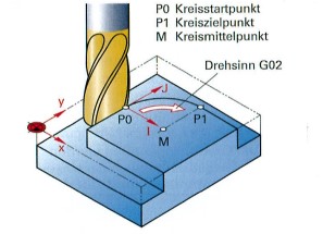
The axes X, Y and Z are assigned the coordinates I, J and K for the position of the centre of the circle M. According to DIN, the coordinates I, J and K are used to specify the distance from the start of the circle to the centre of the circle M incrementally, even if the distance condition G90 (absolute dimension) has been programmed.
Image: Circular interpolation
For machine controls (e.g. DIN control), the position of the centre point M can also be specified with the radius of the circle.
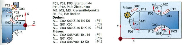
Image: Circular interpolation during turning and milling
Programming of workpiece contours
The two programmes for a milled part and a turned part to be finished only contain the path conditions and the coordinate values for machining the workpiece contour. The destination point to be approached is programmed as the coordinate value in each block.
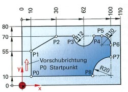
Picture: Base plate
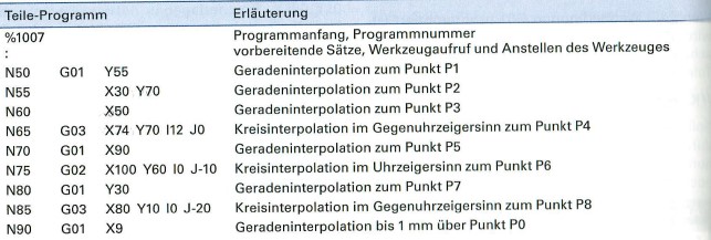
Table 1 contains a programme extract with explanations for CNC milling the base plate
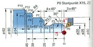
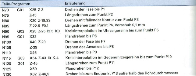
Table 2 contains a programme extract for CNC turning (finishing) of the shaft journal with explanations. The workpiece contour is usually programmed with absolute dimensions (G90).
Image: Turning (finishing) a shaft journal
All X coordinate values are specified in diameter so that the drawing dimensions can be adopted during programming. In the Z direction, the end points of the straight lines and circles are programmed from the workpiece zero point. In the case of a circle, the position of the centre point must also be specified with the coordinates I and K.
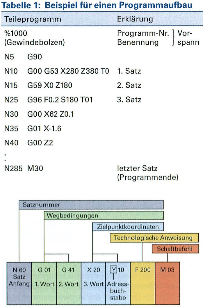
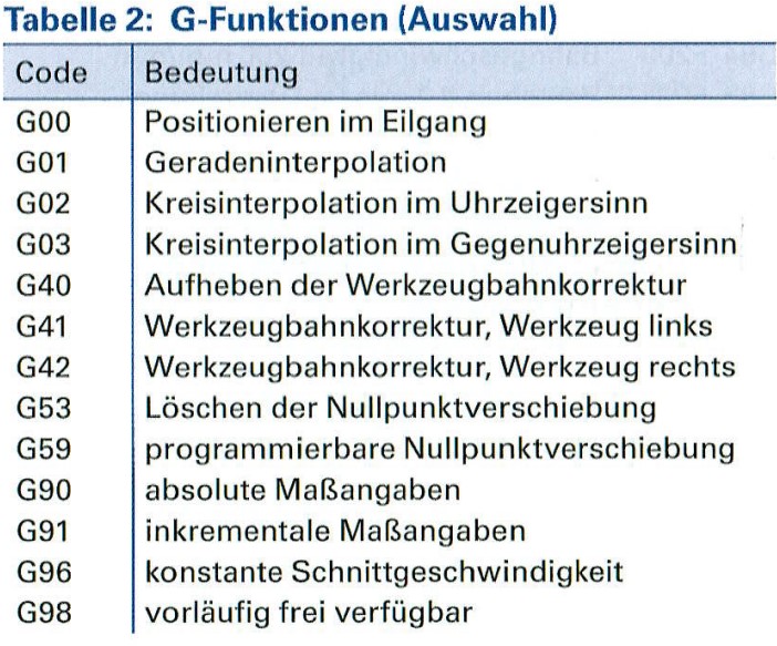
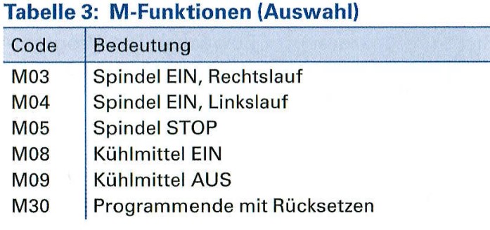
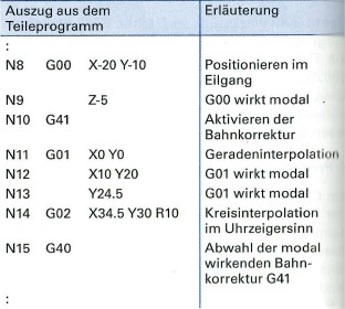
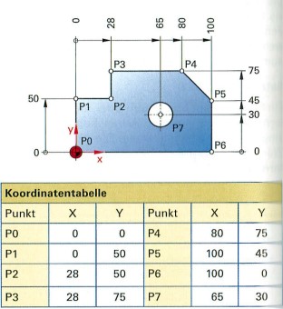 Image: Absolute dimensioning of a panel